Bypassing SEN-08630 PIR motion sensor's voltage regulator to work with 3.3 V
04:31 12.10.2014
Having successfully tested my motion sensor with Raspberry Pi's 5 V output and a multimeter for reading, I had still left one problem to rectify: make it work with only 3.3 volts so I could safely read it with Raspberry.
All the shops say that:
You can also install a jumper wire past the 5V regulator on board to make this unit work at 3.3VHowever, nobody ever tells how.
At this point, I am, as a beginner, who doesn't even know how a voltage regulator might look like, a bit fucked.
Thankfully, with a little googling, Adafruit is here to the rescue.
Although not exactly the same board, at least there is a map and I now have a clue how that regulator looks like. And really - there is something very similar on my board too:
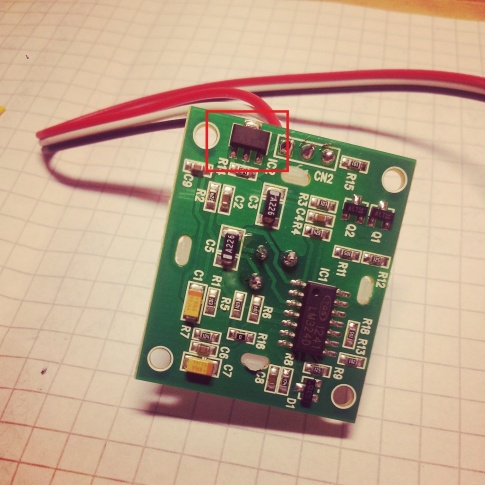
Voltage regulator on SEN-08630 PIR motion sensor board.
So, after some tests with a multimeter, I decided that I need to jump the outer pins and that would be it.
Finally, a jumper wire to be soldered:
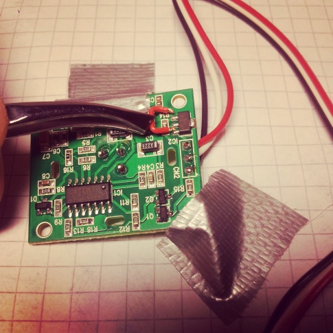
Final solution to the voltage question.
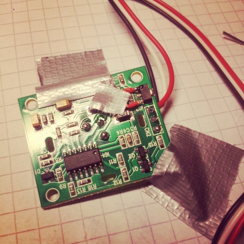
Sensor board and jumper duct-taped in place for soldering, almost done.
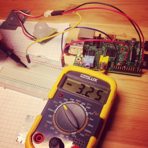
Bypass successful - testing with a multimeter and a self-made pull-up resistor.
Up and running with just 3.3 V, it was time to test reading motion with a little piece of software.
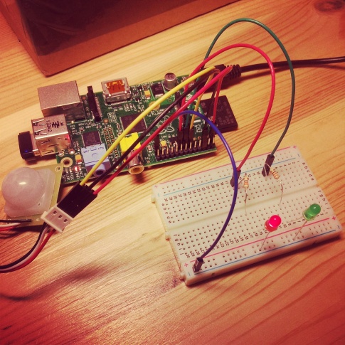
And, finally, some more fun.
Oppa Allman Style:
#include <stdio.h>
#include <wiringPi.h>

int main (void)
{
	wiringPiSetup();
	pinMode(0, INPUT);
	pullUpDnControl(0, PUD_UP);
	pinMode(2, OUTPUT);
	pinMode(3, OUTPUT);

	int status = 1; // Off by default
	for (;;)
	{
		status = digitalRead(0);

		printf("PIR: %d", status);
		printf("\r");
		fflush(stdout);

		if (status == 0)
		{
			digitalWrite(2, 0);
			digitalWrite(3, 1);
		}
		else
		{
			digitalWrite(2, 1);
			digitalWrite(3, 0);
		}

		delay(200);
	}

	return 0;
}
Compile and link with Wiring Pi:
gcc -Wall -o pir pir.c -lwiringPi
And here we go: