Quick2Wire Analog Board and Raspberry Pi
22:06 20.04.2014
As soon as I received my Quick2Wire Analog Board I couldn't wait to get it up and running.
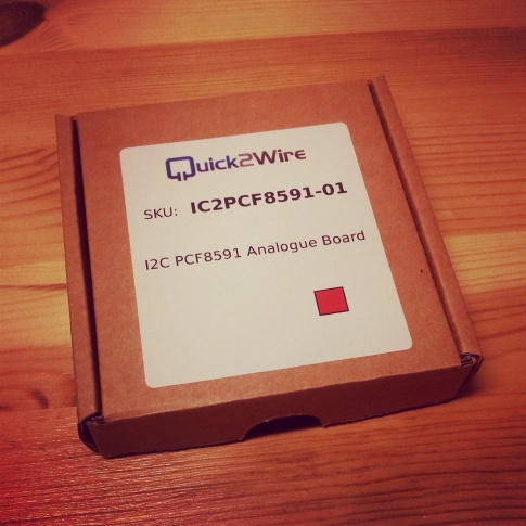
Quick2Wire Analog Board shipped in a small, nice box.
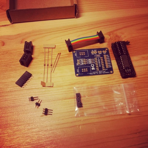
All the parts of the board.
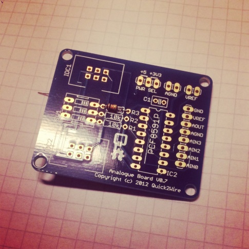
I had never soldered anything so small ( even this is nothing small in the world of electronics ) with solder points so close to each other, but hopefully my soldering iron was small enough to get this job done and I was ready to roll...
In the official assembly guide they start with a capacitor, however, I decided to leave that for later - because I hadn't any special device to hold the board and I didn't want anything relatively high and with just two thin legs as that capacitor on it while I try soldering other parts on, just to eliminate the possibility of accidentally breaking it off.
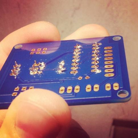
Three resistors, on the other hand, seemed pretty rigid and low profile for me, and SW1, 6-legged addressing switch, would be an obstacle to one side of resistor soldering spots if trying to place them on later.
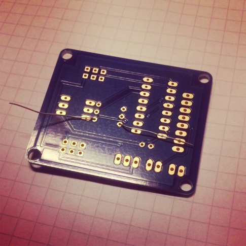
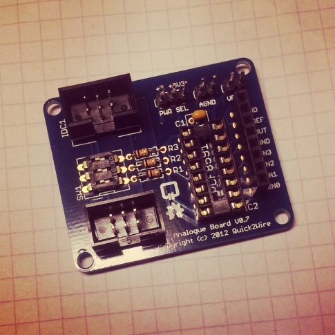
I got them all in place, but, as I feared to accidentally solder the spots together, I used as little solder I could. So it was not very visually aesthetic:
As for the other components, I continued in the order described in the assembly manual.
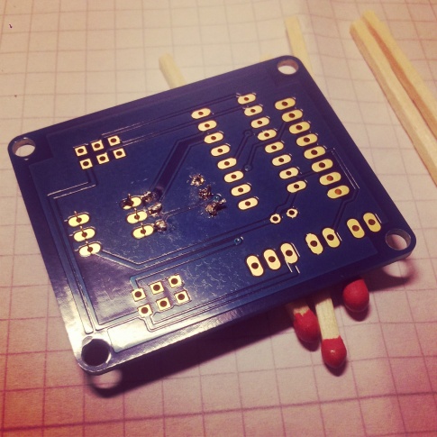
A few matches to keep the board leveled while soldering the addressing slide switch.
After a dozen and a bit more pins soldered, my soldering was looking a bit less terrible.
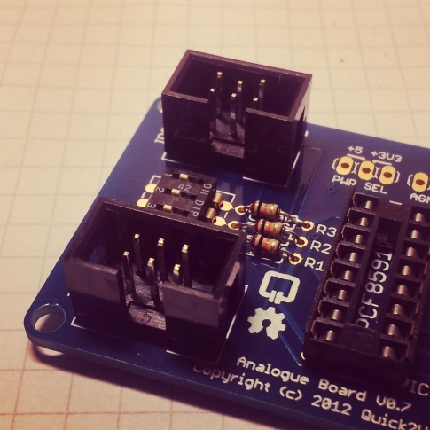
Then, at the 6-pin IDC headers, I encountered a problem. As I couldn't solder the pins quick enough, they melted out of the plastic and started to slide out of the place... It wasn't a very easy task to put them back again, as I was one hand short. One for holding the board, the second for the soldering iron, and then the the third could have become handy to push the pin back in.
Somehow I managed to do it with only two hands available, practicing some finger yoga and burning the finger I used to push the pin. Still, yet better, pins were not exactly perfect, as you can see with both the top left and the right pin in the upper connector:
By this time, the board was stable enough when upside down, so it was ready for the capacitor:
There was another problem when I got to the jumpers: they were the first ones that didn't stay well in the position before soldering, so I made them to, MacGyver style:
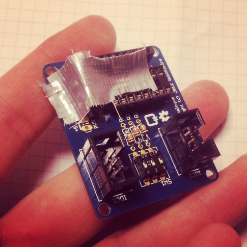
If it moves, but it shouldn't, use duct tape.
And done:
To insert the chip you have to bend the pins first so they are not too widely spread for the socket, and it was a bit scary; what if I somehow break them off even before getting this thing to run? But after bending them gently, checking if it fits and bending some more, I finally got the chip placed:
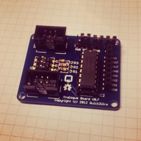
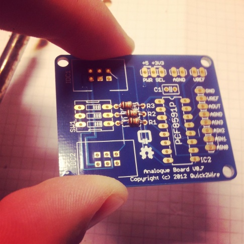
Fully assembled, 3-pin jumper set to power the board with 3.3 V from the Raspberry Pi.
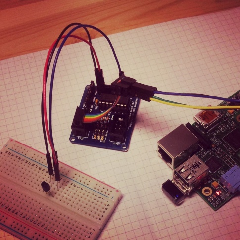
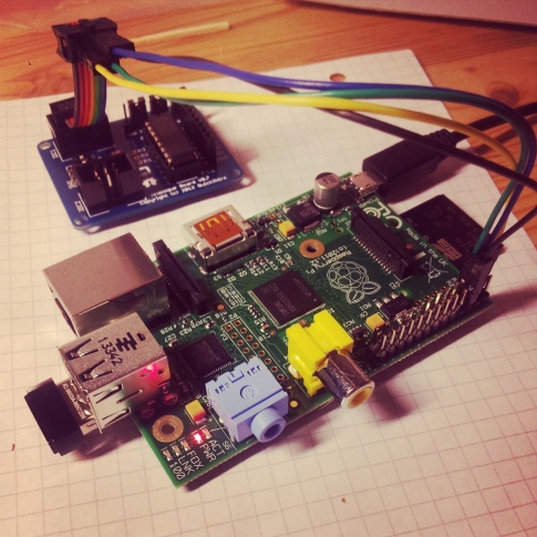
The board is originally designed to be used together with a Quick2Wire Interface board, and if doing so, you just plug the Interface Board to Raspberry's GPIO and the Analog Board directly to the Interface Board's I2C header.
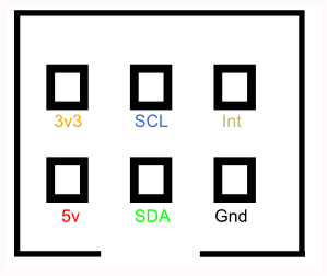
I had to plug it directly to my Raspberry, so I googled up an I2C pinout...
... and was ready to test the board, just an hour after I had all this started.
To use I2C on Raspberry Pi, I enabled two kernel modules ( they are off by default, but it is possible to turn them permanently on, so you don't have to do this every time you want to do something with I2C ):
[root@alarmpi ~]# modprobe i2c-dev
[root@alarmpi ~]# modprobe i2c-bcm2708
Then installed I2C toolkit:
[root@alarmpi ~]# pacman -S i2c-tools
Finally, looked for my board, but got nothing:
[root@alarmpi ~]# i2cdetect -y 1
     0  1  2  3  4  5  6  7  8  9  a  b  c  d  e  f
00:          -- -- -- -- -- -- -- -- -- -- -- -- --
10: -- -- -- -- -- -- -- -- -- -- -- -- -- -- -- --
20: -- -- -- -- -- -- -- -- -- -- -- -- -- -- -- --
30: -- -- -- -- -- -- -- -- -- -- -- UU -- -- -- --
40: -- -- -- -- -- -- -- -- -- -- -- -- -- -- -- --
50: -- -- -- -- -- -- -- -- -- -- -- -- -- -- -- --
60: -- -- -- -- -- -- -- -- -- -- -- -- -- -- -- --
70: -- -- -- -- -- -- -- --
I had no idea what could have been wrong, but my lack of soldering expierence suggested that I probably did a bad job that now needs reworking. Pulled out the chip to prevent it from overheating while resoldering pins for its socket, when I realized what was actually wrong.
As I had no female-female wires, I had to use male-female that came with my Starter Kit A in a combination with I2C connector from the Analog Board Kit. So I looked at the pinout picture, put the males in the connector and females on the Raspberry's GPIO. But the picture was for the socket, not the connector which is mirrored when looking "from below": I had exchanged SDA for SCL, 3v for 5v and GND for Int.
Hoping that the board wasn't already damaged beyond repair, I fixed the wiring and tried again...
Still no luck, but only because I forgot to put the chip back in, LOL. Disconnected the board, put it back, and here we go - address #48, here it was:
[root@alarmpi ~]# i2cdetect -y 1
     0  1  2  3  4  5  6  7  8  9  a  b  c  d  e  f
00:          -- -- -- -- -- -- -- -- -- -- -- -- --
10: -- -- -- -- -- -- -- -- -- -- -- -- -- -- -- --
20: -- -- -- -- -- -- -- -- -- -- -- -- -- -- -- --
30: -- -- -- -- -- -- -- -- -- -- -- UU -- -- -- --
40: -- -- -- -- -- -- -- -- 48 -- -- -- -- -- -- --
50: -- -- -- -- -- -- -- -- -- -- -- -- -- -- -- --
60: -- -- -- -- -- -- -- -- -- -- -- -- -- -- -- --
70: -- -- -- -- -- -- -- --
To furher test the board I got WiringPi GPIO utility:
[root@alarmpi ~]# pacman -S wiringpi
Testing is very easy with this toolset - here is a good article on that.
First, I tried analog reading:
[root@alarmpi ~]# gpio -x pcf8591:120:0x48 aread 120
2
"-x pcf8591:120:0x48" option tells the utility that I want to use a PCF8591 chip, an analog-digital converted used by the Q2W board, using 120 as a base for its pin numbering ( so that the 0th pin will be addressed as 120, 1st - 121, 2nd 122 and so on; as I found out, choosing exactly 120 in this example is meaningless as you can choose any other base as you want, with some constraints, but basically that has no effect on anything ), with an address of hexadecimal 48, 0x48 - the one told me by the "i2cdetect" utility.
When you have ground attached to a pin you want to read, it should read 0; selected operating voltage - 3.3 or 5 V - should read 255; something between - well, something between. And if there is nothing attached, the reading is random and unpredictable.
I tried linking the pin with ground and tried with a plus, however, I was getting some apparently erroneous readings - always random instead of exactly 0 and 255 as expected.
At that time I had no multimeter, so I couldn't double check, all my testing needed to be done with a software. :)
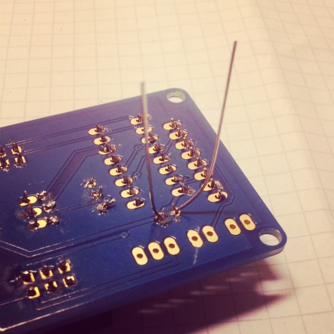
Had better luck with writing though. Placed a LED and did an analog write 255 - full throttle, but the LED only glowed a little. When I took the board with my hands, it went off completely, so I tried moving the female input/output header a bit - and it suddenly was fully bright as it should have been.
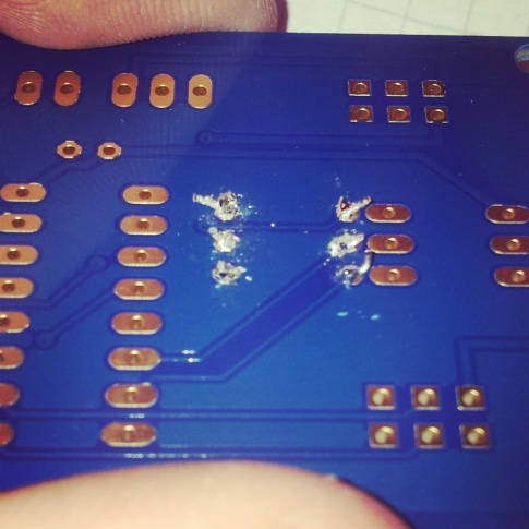
It was now quite obvious that my soldering was bad, and after checking I noticed that some pins were barely touching the solder mountain elevating from the board. So I quickly had this repaired, soldering with larger amount of solder and from both sides of the pins, not just one as I had done before.
So I learned not to be afraid of soldering something together and my board was working perfectly from that time on.